Septic system diagram: every component explained
By the SepticMind Editorial Team

TL;DR
- A conventional septic system has four main parts: the inlet pipe from the house, a buried concrete or plastic tank that separates solids from liquid, a distribution box that splits the flow, and a drain field where clarified wastewater soaks into the soil.
- Knowing how each part connects tells you exactly where failures start and what to fix first.
What does a septic system diagram actually show?
A septic system diagram is a cross-section map of how wastewater moves from your toilets and drains, underground, and finally into the soil. It is not a plumbing diagram of the house. It starts where your main sewer line exits the foundation and ends hundreds of feet away in the drain field.
Most diagrams show five zones: (1) the house outlet and inlet pipe, (2) the septic tank interior with its inlet baffle, outlet baffle, and three layers of waste, (3) the effluent line leaving the tank, (4) the distribution box or manifold, and (5) the drain field trenches with perforated pipe and gravel or chamber systems. Some systems add a pump chamber between the tank and field if the lot is flat or the field sits uphill.
The EPA's SepticSmart program describes the basic design this way: wastewater flows from the home into the septic tank, where "heavy solids settle to the bottom, forming sludge, while greases and lighter solids float to the top, forming scum." The liquid layer in between, called effluent, exits through the outlet baffle and flows to the drain field [1].
Diagrams vary by system type. A conventional gravity system looks nothing like a pressure-dosed system, a mound system, or an aerobic treatment unit (ATU). This article covers the conventional gravity system first, then flags where the other types diverge.
What are all the parts labeled on a septic system diagram?
Here is every component you will see on a standard diagram, in flow order.
Inlet pipe (building sewer)
This is the 4-inch PVC or cast-iron pipe that carries all household wastewater from the foundation to the tank. It slopes downhill at a minimum of 1/8 inch per foot, though 1/4 inch per foot is more common under most state plumbing codes. The pipe runs underground, roughly 12 to 24 inches deep at the house wall and deeper as it reaches the tank.
Septic tank
The tank is a watertight buried container, most often precast concrete, though fiberglass and polyethylene tanks are legal in many states. Residential tanks range from 750 gallons (older installs) to 1,500 gallons or more. The EPA recommends a minimum 1,000-gallon tank for a home with up to three bedrooms [1]. Inside the tank you find:
- Inlet baffle or tee: slows incoming wastewater so it does not disturb the settled sludge; typically extends 6 to 8 inches below the liquid surface.
- Scum layer: fats, oils, and floating solids at the top, kept below the outlet tee opening.
- Effluent (clear zone): the liquid middle layer that flows out.
- Sludge layer: heavy solids that settle to the bottom and build up over time.
- Outlet baffle or tee: keeps scum from escaping to the field; extends about 30% of liquid depth below the surface.
Some tanks are two-compartment, which gives solids a second settling chamber before effluent leaves the tank. Many states require two-compartment tanks for new installs.
Access risers and lids
Manhole risers (12 to 24 inches in diameter) extend from the tank top to grade so the tank can be pumped without excavation. Older systems often have no risers. Adding them is one of the better maintenance investments you can make. See septic tank riser for details on retrofitting.
Effluent line
A solid (non-perforated) pipe runs from the tank outlet baffle to the distribution device. This pipe also slopes downhill, typically 1/8 to 1/4 inch per foot. It has to be watertight. Any crack here soaks the soil before water even reaches the field.
Distribution box (D-box) or manifold
The D-box is a small concrete or plastic box that splits flow evenly among the drain field trenches. Each outlet port should sit at the same elevation so one trench does not get more flow than the others. Uneven distribution is a leading cause of early drain field failure.
Drain field (leach field)
This is where treated effluent leaves the pipe and soaks into the soil. A conventional drain field has perforated 4-inch pipe set in 6 to 12 inches of washed gravel (3/4 to 1.5 inch diameter), covered with geotextile fabric, then backfilled with soil. Trenches run 18 to 36 inches wide and 18 to 36 inches deep, though required dimensions vary by state. Pipe is level within each trench (no slope) so flow spreads the full length.
Soil absorption zone
Below the gravel, the biomat forms. It is a thin biological layer that polishes effluent as it moves through. A healthy biomat is a feature, not a problem. An overgrown biomat is what fails the field.
Reserve area
Many jurisdictions require a reserve drain field area, usually equal to 100% of the primary field size, left undisturbed in case the primary field fails. You will see it labeled on site plans.
How does the septic tank connect to the drain field?
The connection between tank and field is the most misunderstood part of the whole diagram. Homeowners assume the tank treats waste and the field just gets rid of it. The reality is the opposite of what most people think. The tank only removes solids. The field does most of the treatment.
Effluent leaving the tank still carries heavy biological oxygen demand (BOD), nitrogen compounds, and pathogens. As it moves through 2 to 4 feet of unsaturated soil below the trench bottom, bacteria, filtration, and adsorption cut those contaminants to safe levels before the water reaches groundwater. That soil treatment is exactly why setback distances from wells matter so much [1].
This is also why the outlet baffle earns its keep. If it cracks or corrodes (common in older concrete tanks), floating scum escapes to the field. Solids clog the gravel pores, the biomat overgrows, and the field backs up. Tank neglect leading to field damage is the most expensive path in residential septic ownership. A septic tank pump out every three to five years prevents it.
Pressure-dosed systems add a pump chamber after the tank. A timer or float switch fires a pump on a schedule, pushing small, frequent doses of effluent to the field through small-diameter pressure pipe and emitter holes. Dosing rests the field between cycles, which stretches field life. The diagram for a pressure system labels the pump chamber with its float assembly, pump, and alarm float alongside the standard components.
What do the layers inside the septic tank look like in cross-section?
Slice a septic tank vertically and look at it from the side, and you see three distinct horizontal bands.
The scum layer sits at the top, roughly 6 to 12 inches thick in a well-kept tank. It is mostly fats, grease, and floating paper. The outlet baffle opening sits below the bottom of this layer so scum cannot escape.
The clear zone (effluent) takes up the middle and largest volume of the tank. This is the liquid that flows out to the field. It is not clean water. It is lightly treated wastewater with dissolved organics and pathogens, but it is free of floating and settled solids.
The sludge layer sits on the tank floor. Sludge builds up at roughly 1.5 to 2 cubic feet per person per year in a typical household, though diet, garbage disposal use, and household size all move that number [2]. Once the combined depth of sludge and scum eats more than one-third of the tank's liquid volume, solids start escaping to the field. That is the functional threshold for pumping.
A good pumper measures scum and sludge depths with a long rod and a velcro strip (the Bretz stick method) before pumping, to document conditions. If your pumper skips this, ask for it. The measurement tells you how fast your tank fills and when it actually needs service, which beats any calendar schedule.
For pump-out intervals by household size, see how often to pump septic tank.
What does a septic drain field diagram look like from above and in cross-section?
From above (plan view), a conventional drain field looks like a set of parallel trenches, usually three to five, arranged like fingers reaching out from a central D-box. Each trench runs 50 to 100 feet long and sits at least 6 feet apart center to center so the soil and root zones between trenches keep working.
In cross-section, the trench is a rectangular cut in the soil. Top to bottom: 6 to 12 inches of topsoil and grass, then the geotextile fabric barrier, then the gravel layer with the perforated pipe resting on 6 inches of gravel and 2 inches of gravel covering the pipe top, then native soil below. Total trench depth is typically 24 to 36 inches.
Chamber systems (manufactured plastic arch units like the Infiltrator brand) replace the gravel and pipe. The cross-section shows the plastic arch sitting on native soil, storing effluent in the void space during peak flow, then letting it soak in gradually. Chamber systems need less excavated volume and are common in many states now because they perform on par with gravel systems using less material and labor.
The plan view also shows the reserve area, usually flagged or fenced. Never park vehicles, plant trees, or build over or near the drain field or reserve area. Root intrusion and soil compaction are the two most common physical causes of drain field failure.
For field function and failure patterns in full, the septic drain field guide covers it.
What are the setback distances labeled on a septic system site plan?
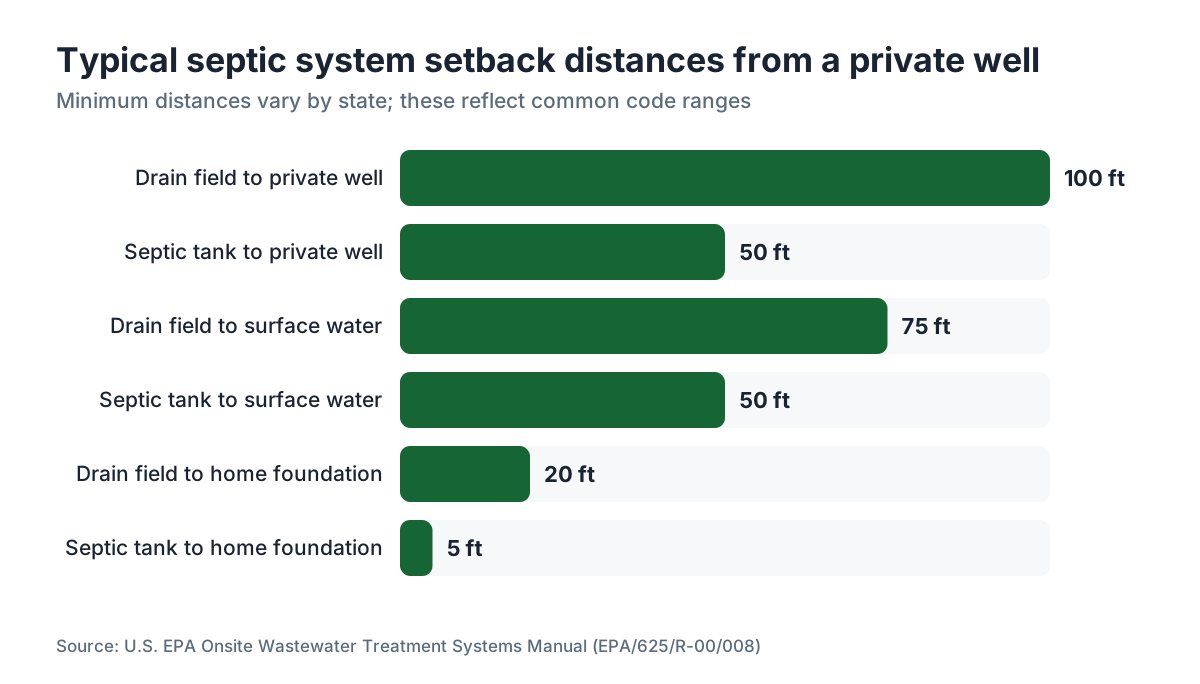
Setback distances appear on every professional site plan. They define how far each component has to sit from wells, property lines, surface water, buildings, and other features. State and local codes set them, not federal rules, so they vary a lot.
The table below shows representative setback requirements from several states so you get a sense of the range. Your jurisdiction may differ, and your local health department or extension service is the authoritative source [3].
| Component | From private well | From surface water | From property line | From foundation |
|---|---|---|---|---|
| Septic tank | 50 ft (common minimum) | 50 ft | 5-10 ft | 5-10 ft |
| Drain field | 100 ft (common minimum) | 50-100 ft | 10 ft | 20 ft |
| Effluent line | 50 ft | 25 ft | varies | 5 ft |
These are illustrative ranges drawn from EPA guidance and common state codes [1][3]. Some states (Florida, for example) require 75 feet from a private well to a drain field. Others go to 150 feet for certain soil types. Pull your state's onsite wastewater rules before designing or siting a system.
If your diagram shows any component closer to a well than the minimum setback, that is a legal and health problem, and a licensed designer needs to evaluate it. Setback violations found during a real estate sale routinely kill transactions or force system relocation.
How do alternative system diagrams differ from a conventional one?
Not every lot can take a conventional gravity system. When soil percolation is too slow or too fast, the lot is too small, or the seasonal high water table sits too close to the surface, designers turn to alternative systems. Each has its own diagram.
Mound system
A mound system diagram shows a raised earthen mound, typically 2 to 4 feet above original grade, built over the existing ground surface. The tank still sits in-ground. A pump chamber doses effluent up to the mound through small-diameter pressure pipe. The mound holds sand fill, perforated distribution pipe, gravel, and topsoil cover. The side view looks like a gentle hill with the distribution network inside. Mound systems cost a lot more than conventional systems, often $10,000 to $20,000 more at installation [4].
Aerobic treatment unit (ATU)
An ATU diagram looks busier because it adds a treatment tank with an air blower, mixing, and often a chlorination or UV disinfection chamber before effluent reaches the field. ATUs produce much cleaner effluent (secondary or tertiary treatment level), which allows smaller drain fields or, in some states, discharge to surface water. They require a maintenance contract in most jurisdictions.
Low-pressure pipe (LPP) system
LPP diagrams show a pump chamber with a timer dosing effluent through small-diameter (1.5 to 2 inch) pressure pipe to perforated laterals. The field trenches are shallower than conventional systems, which helps in areas with high water tables.
Drip irrigation system
A drip system diagram shows a filter unit, a pump, and subsurface drip tubing set just 6 to 18 inches below the root zone. These are common on difficult lots in western states and need careful maintenance of the filter assembly.
Whatever the system type, the same diagnosis works: trace the diagram from house to field, check each component in sequence, and the failure sits in the zone where flow stops.
How do you read a septic system diagram for a home inspection or real estate purchase?
A septic diagram (usually a site plan stamped by the original designer or the health department) tells you several things a visual inspection cannot.
First, confirm the tank size matches the home's bedroom count. Most states size tanks by bedroom count because bedroom count predicts maximum occupancy. A 1,000-gallon tank on a 4-bedroom house in a state that requires 1,500 gallons is undersized and possibly unpermitted [1].
Second, check the drain field size against the soil type noted in the perc test or soil evaluation report. The drain field area (total square feet of trench bottom or infiltration surface) has to meet the required loading rate for that soil. Sandy soils accept more gallons per square foot per day than clay-heavy soils.
Third, look for the reserve area. If the original diagram shows none, ask whether the lot even has room for one. In many older rural subdivisions it does not, which means a failed field has nowhere to go except a very expensive engineered alternative.
Fourth, count the years. A conventional drain field in sandy loam soil can last 30 to 50 years with good maintenance [5]. A field that has never been pumped and is 25 years old may be near end of life no matter how it looks today.
During a pre-purchase inspection, a licensed inspector runs dye tests and checks the tank condition. But the paper diagram, pulled from county records, is the foundation. Many counties have digitized these records. Check your county environmental health office.
For what installation involves and what drives cost, see septic tank installation and cost to install septic system.
What maintenance does each part of the diagram require?
Every component in the diagram has its own maintenance needs and failure modes. Here is a working maintenance map.
Inlet pipe: Check for root intrusion and offset joints every 5 to 10 years, especially with older clay or cast-iron pipe. Camera inspection costs $150 to $400 and earns its keep before any major system work [6].
Septic tank: Pump every 3 to 5 years for a typical household, though the right interval depends on tank size, occupancy, and measured sludge buildup. EPA SepticSmart guidance calls routine pumping the single most effective maintenance action a homeowner can take [1]. The septic tank cleaning article has the full interval table. Keep the inlet and outlet baffles intact. Plastic effluent tee baffles ($10 to $30 in parts) are easy to swap when the tank is open.
Access risers and lids: Inspect lids yearly for cracks. A cracked concrete lid is a fall hazard and lets rainwater into the tank, which can hydraulically overload the field during storms.
Distribution box: Inspect it every time the tank is pumped. Look for uneven outlet elevations (adjust with shims or grout) and root intrusion. A D-box costs $50 to $200 to replace if it cracks.
Drain field: Protect it. No vehicles, no deep-rooted trees within 30 feet, no paving over it. Route roof drains and sump pumps away from the field. Sewage odors at the surface, wet or spongy ground, and slow drains or backups in the house all point to field trouble.
Some homeowners reach for septic tank drain field cleaner products (enzyme or bacterial additives) hoping to revive a struggling field. The evidence for these products is thin. University of Minnesota Extension reviewed the available studies and found insufficient evidence that bacterial additives improve system performance or extend field life [7]. Regular pumping and load reduction (water conservation, no garbage disposal use) are the strategies that hold up.
Operators running multiple service routes can use tools like SepticMind to track pump-out histories and flag which properties are overdue based on tank size and household data, which cuts the guesswork at scale.
See septic tank pumping for the full pump-out process and what it costs.
What do common failure points look like on the diagram?
Know the diagram and you diagnose failures much faster. Here are the most common failure scenarios mapped to diagram components.
Backup to the house (all drains slow, or sewage comes up)
Start at the D-box or the tank outlet. If the tank is full of effluent and the field looks saturated, the field is the likely culprit. If the tank liquid level is normal but the inlet is submerged, the inlet pipe is blocked. That means a septic tank repair or septic system repair call.
Wet spot or odor over the drain field
This is almost always a hydraulically overloaded or clogged field. Check the D-box first for uneven flow. One trench taking all the flow fails early while the others stay healthy. Redistributing flow by leveling the D-box sometimes buys years of field life.
Sewage smell near the tank but no backup
A cracked riser lid, a corroded outlet baffle letting gases back up, or a broken effluent line between tank and D-box. The diagram tells you where to look: the smell source is almost always within 20 feet of the tank.
Pump alarm going off (pressure systems)
The pump chamber float trips on high water, meaning either the pump has failed or the field cannot take the dose. Check the pump first (a simple float test). If the pump runs but the water level does not drop, the field is the problem.
Nobody has great national data on failure rates by component. The closest study, a survey of septic systems in the Puget Sound region, found that roughly 25% of systems inspected had at least one component deficiency, with outlet baffle failure and drain field stress being the two most common findings [8]. That number is probably representative of older housing stock nationally, though local conditions swing widely.
Where can you find your property's actual septic system diagram?
Your system's as-built diagram (sometimes called a record drawing or as-built card) should be on file with your county or local health department. Most jurisdictions recorded these at permit issuance, and many have digitized records going back 20 to 40 years.
Start with your county environmental health department website. Search for "as-built records," "septic records," or "onsite wastewater." You will usually need your parcel number or address. Some counties charge a small retrieval fee ($5 to $25). In many states, this record is public information.
If county records come up short (common for systems installed before the 1970s or in rural areas with light oversight), the next sources are the original homebuilder's records, your title insurance company, a previous owner, or a licensed septic inspector who can probe the yard and locate components with a soil probe.
Your state's onsite wastewater program website is another resource. The EPA maintains a directory of state programs [9]. State extension services (land-grant university cooperative extension programs) publish region-specific diagrams and sizing guides for free [7][10].
Once you have the diagram, scan it and keep a digital copy. You will need it for any future permit, inspection, or sale. If the diagram shows a system that was modified without permits (added bedrooms, relocated components), that is a disclosure issue in most states.
Frequently asked questions
What is the difference between a septic tank and a drain field on a diagram?
The septic tank is a buried, watertight container that separates solids from liquid. It does not treat water, it just settles it. The drain field is the network of perforated pipes and gravel (or plastic chambers) where clarified liquid soaks into the soil and gets treated biologically. On a diagram, the tank is a rectangular box near the house, and the drain field is the set of parallel lines extending away from it.
How big is a typical septic tank and drain field for a 3-bedroom house?
For a 3-bedroom home, most state codes require a minimum 1,000-gallon septic tank, though 1,250 gallons is more common in newer installs. The drain field size depends on soil percolation rate. Typical sizing runs 300 to 500 square feet of trench bottom per bedroom, putting a 3-bedroom field at 900 to 1,500 total square feet of absorption area. Sandy soils need less area than clay soils.
What does the inlet baffle do and what happens if it fails?
The inlet baffle slows incoming wastewater and directs it downward into the tank's liquid zone instead of blasting across the surface and stirring up settled sludge. If the baffle fails or corrodes away, incoming flow churns the sludge and can push solids out to the drain field much earlier, clogging the gravel and shortening field life. Inspecting and replacing baffles at every pump-out is cheap insurance.
What is a distribution box and where does it appear on the diagram?
A distribution box (D-box) is a small concrete or plastic chamber between the septic tank and the drain field. It receives the single effluent line from the tank and splits flow equally among the drain field laterals. On a septic drain field diagram it appears as a small square or rectangle at the head of the trench network. If its outlet ports sit at uneven elevations, one trench gets overloaded and fails first.
Do septic tank drain field cleaner products actually work?
The honest answer is probably not in any way that matters. University of Minnesota Extension reviewed the research and found no reliable evidence that bacterial or enzyme additives improve septic system performance or extend drain field life. A healthy tank already holds billions of active bacteria. What does help: regular pumping to keep solids out of the field, reducing water loads, and avoiding antibacterial soaps and large volumes of bleach.
How deep is a septic drain field below the surface?
Conventional drain field trenches run 18 to 36 inches deep, measured from the ground surface to the trench bottom. The perforated distribution pipe sits about 6 inches above the trench bottom, covered by 2 inches of gravel on top. In colder climates, trenches go deeper to get below frost depth. The actual depth on your property depends on your local code and the original installer's design.
What is the reserve drain field area shown on the site plan?
The reserve area is a part of your lot set aside for a future replacement drain field if the primary field fails. Many state codes require it to equal 100% of the primary field size. It has to stay undisturbed: no structures, no paving, no deep-rooted landscaping. If your diagram shows no reserve area, your property may face very expensive options if the primary field fails.
How does a mound system diagram differ from a conventional septic diagram?
A mound system adds a pump chamber after the conventional septic tank and shows the drain field raised above grade in an earthen mound. The mound holds sand fill, perforated distribution pipe inside gravel, and a topsoil cover. The side view shows this mound profile, typically 2 to 4 feet above original ground. Mound systems get used when soil is too shallow or the seasonal water table is too high for a conventional in-ground field.
How far should a septic system be from a well?
The common minimum is 50 feet from the septic tank and 100 feet from the drain field to a private drinking water well, but state requirements vary a lot. Florida requires 75 feet from tank to well, and some states go higher for certain system types or soil conditions. These setbacks appear on your site plan and are enforced at permit issuance. If your well and system sit closer than your state minimum, consult your local environmental health department.
What does a two-compartment septic tank look like on a diagram?
A two-compartment tank diagram shows a dividing wall inside the tank with a small submerged port near the top of the wall, separating the inlet zone from the outlet zone. The first compartment takes raw wastewater and handles initial settling. The second compartment gives additional settling before effluent exits to the drain field. Many states require two-compartment tanks for new installations because they cut the solids reaching the field.
How do I find my septic system diagram if the previous owners left no records?
Start with your county environmental health or planning department. Most jurisdictions filed as-built drawings at permit issuance, and many have digitized older records. Bring your parcel number. If county records are missing, a licensed septic inspector can probe your yard with a soil probe and use a metal detector or electronic locator to map buried components and sketch a field diagram. Some states list as-built records through their online permitting portals.
What maintenance intervals apply to the components shown in the diagram?
Pump the septic tank every 3 to 5 years for a typical household (sooner for small tanks or large families). Inspect the inlet and outlet baffles at every pump-out and replace if damaged. Check the distribution box for level outlet ports and root intrusion every 3 to 5 years. Inspect risers and lids yearly for cracks. The drain field needs no active maintenance beyond protecting it from vehicle traffic, tree roots, and excess water loading.
What causes a drain field to fail and how does it show on the diagram?
The most common cause is solids escaping the tank because of deferred pumping or a failed outlet baffle. Those solids clog the gravel pores and overgrow the biomat, blocking infiltration. On the diagram, failure concentrates in the trench closest to the D-box, which takes the most flow. Surface wetness, sewage odors above the field, and slow drains in the house all point to the drain field zone on the diagram.
Sources
- U.S. EPA, SepticSmart: How Your Septic System Works: Wastewater enters the septic tank where solids settle as sludge and greases float as scum; EPA recommends a minimum 1,000-gallon tank for homes up to three bedrooms
- U.S. EPA, Onsite Wastewater Treatment Systems Manual (EPA/625/R-00/008): Sludge accumulates at approximately 1.5 to 2 cubic feet per person per year under typical household conditions
- U.S. EPA, Onsite Wastewater Treatment Systems Manual, Chapter 4: Site Evaluation: Setback distances for septic system components from wells, surface water, and property lines vary by state; EPA manual provides representative ranges
- Penn State Extension, Alternative Septic Systems for Difficult Sites: Mound systems typically cost $10,000 to $20,000 more than conventional systems at installation due to added fill, pumping equipment, and design complexity
- University of Minnesota Extension, Septic System Owner's Guide: A well-maintained conventional drain field in suitable soil can last 30 to 50 years; poor maintenance is the leading cause of early failure
- National Onsite Wastewater Recycling Association (NOWRA), Consumer Guidance: Video camera inspection of inlet pipes costs approximately $150 to $400 and is recommended before major septic system repairs to identify root intrusion and offsets
- University of Minnesota Extension, Additives for Septic Tanks: University of Minnesota Extension review found insufficient scientific evidence that bacterial or enzyme additives improve septic system performance or extend drain field life
- Washington State Department of Health, Onsite Sewage Systems Program: Approximately 25% of systems inspected in a Puget Sound survey had at least one component deficiency; outlet baffle failure and drain field stress were the two most common findings
- U.S. EPA, State Onsite Wastewater Management Programs Directory: EPA maintains a directory linking to each state's onsite wastewater regulatory program for setback rules, sizing codes, and as-built record systems
- North Carolina State University Extension, Septic Systems and Their Maintenance: State land-grant extension programs publish region-specific drain field sizing guides and system diagrams based on local soil conditions and regulatory requirements
- U.S. EPA SepticSmart Week Program Guidance: EPA SepticSmart emphasizes routine pumping as the single most effective maintenance action homeowners can take to protect their septic system
Last updated 2026-07-09